
Contents
1. What the sensor measures
2. Key features
3. Technical specifications
4. Safety information
5. Physical installation
6. Commissioning on a LoRaWAN® network
7. Calibration
8. DIP switch configuration
9. Downlink configuration
10. Debug LED sequence
11. Restore factory settings
12. Maintenance, cleaning & disposal
13. Troubleshooting
14. Support & contact
1. What the sensor measures
The sensor reports the following parameters for the surrounding area. All readings are relative to the mounting location, so background levels will naturally vary from room to room.
|
Parameter |
Range |
Accuracy |
|
CO₂ |
400–5000 ppm |
±60 ppm and ±5% of reading |
|
PM1 / PM2.5 |
1–511 µg/m³ |
±10 µg/m³ (<100 µg/m³); ±10% of reading (≥100 µg/m³) |
|
PM4 / PM10 |
1–511 µg/m³ |
±25 µg/m³ (<100 µg/m³); ±25% of reading (≥100 µg/m³) |
|
TVOC |
1–5000 µg/m³ |
±20 µg/m³ |
|
Temperature |
-10 to +50 °C |
±0.5 °C |
|
Humidity |
0–100% RH |
±5% RH |
2. Key features
- Measures CO₂, TVOC, particulate matter (PM1/PM2.5/PM4/PM10), temperature and relative humidity from a single device.
- Reports air quality every 5–60 minutes (configurable; default 15 minutes, with a random ±2 minutes to avoid transmission collisions).
- A test button sends radio messages on demand for commissioning and signal checks.
- Configurable via on-board DIP switches or remotely via LoRaWAN® downlink.
- Transmits wirelessly via LoRaWAN® on licence-free ISM bands, with long-range, low-power communication.
- RESET Air accredited.
3. Technical specifications Measurement
|
Transmission rate |
Every 5–60 minutes (default 15 minutes), with a random ±2 minutes to avoid data transmission collisions |
|
Parameters |
CO₂, temperature, humidity, TVOC and particulate matter (PM1, PM2.5, PM4, PM10) |
|
See also |
Section 1 for full measurement ranges and accuracy |
Power
|
Device input |
5V DC |
|
Power source |
External DC power supply (provided) |
|
Connector |
Barrel Type N, 2.5 × 5.5 mm |
|
Power consumption |
Max 500 mA / 2.5 W |
|
Mains adaptor |
100–240 VAC, 50–60 Hz; interface USB-A plug / Type N barrel connector |
Wireless
|
Protocol |
LoRaWAN® Specification 1.0.1 |
|
Device class |
Class A |
|
Radio frequency |
EU868 (863–870 MHz) |
|
Tx power |
+14 dBm |
|
Sensitivity |
-146 dBm |
|
Security |
LoRaWAN® end-to-end encryption (AES-CTR); data integrity protection (AES-CMAC) |
|
Join method |
OTAA (Over-The-Air Activation) |
Enclosure & dimensions
|
Material |
ABS plastic |
|
IP rating |
IP2X |
|
Dimensions |
110 × 110 × 38 mm (approx) |
Environment & electrical safety
|
Operating temperature |
-10°C to +55°C |
|
Storage temperature |
-20°C to +55°C |
|
Relative humidity |
Max 90% RH up to 31°C, decreasing linearly to 50% RH at 40°C (non-condensing) |
|
Altitude |
Up to 2,000 m |
|
Pollution degree |
PD2 |
|
Overvoltage category |
Category II |
|
Equipment classification |
Class II (double insulated) |
|
Installation |
Indoor use only |
Compliance
CE approved, UKCA compliant, RoHS compliant, WEEE Directive compliant, FCC compliant and RESET Air accredited. The product complies with the UK Radio Equipment Regulations 2017 and Directive 2014/53/EU. Part number: SR_LIN_IAQ_L868.
4. Safety information
|
WARNING If this equipment is used in a manner not specified by the manufacturer, the protection provided by the equipment may be impaired. Read these instructions before use and retain them for reference. Installation should be carried out by competent personnel. |
Health & usage considerations
- Use the device for its intended purpose only, and indoors only.
- Avoid exposure to moisture, dirt and dust.
- Avoid direct sunlight and external heat sources.
- Do not place the device in a metal enclosure, as this may impair wireless communication.
- Do not open the device. In case of an error, contact the manufacturer.
|
Note Prolonged exposure to conditions outside the normal operating range (above 90% RH) may result in temporary signal offset and accelerated component ageing. |
5. Physical installation
Positioning considerations
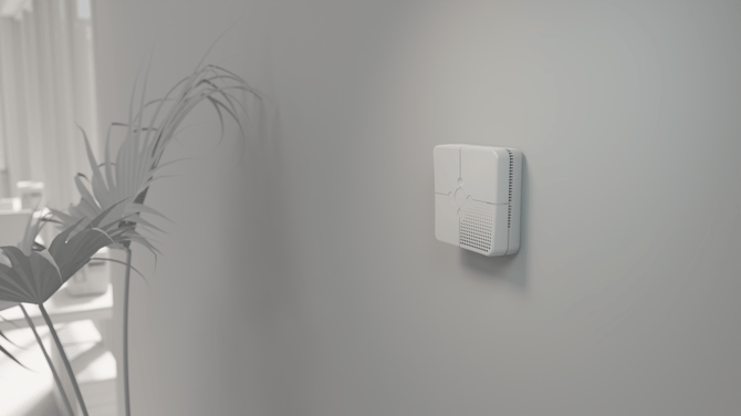
- Mount the sensor at a height of about 1.8 m (head height) on an internal wall for the best readings.
- Keep it away from heat sources, external doors, windows and ventilation, as these can affect readings.
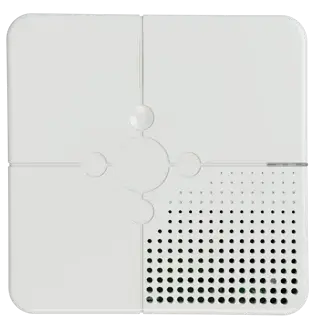
- For the best particulate matter readings, point the vents downward and set the auto-clean function to 1 day.
- All sensing parameters are relative to the mounting location, so background levels will vary.
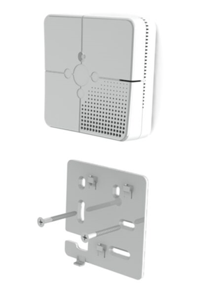
Wall mounting
- Fit the backplate to the wall using the provided screw kit and the recommended fixing slots.
- Remove the breakout clip from the backplate.
- Attach the power supply to the sensor.
- Slide the sensor onto the backplate until it clicks into place — it is then securely mounted.
|
Before commissioning During initial setup, verify that the appropriate DIP switches are enabled (see Section 8). The sensor can also be desk-mounted using the rubber feet instead of wall fixing. |
6. Commissioning on a LoRaWAN network
- Ensure your sensor is powered and within range of your LoRaWAN gateway or receiving device.
- Input the DEV EUI, APP KEY and JOIN EUI into your LoRaWAN Network Server (LNS).
- Power on the sensor and wait for it to connect to the network via OTAA.
- While connecting, the LED flashes BLUE. Once connected to the LNS successfully, the LED blinks GREEN twice.
Decoding the data
Once the sensor is added to your Network Server, decode the information using the Pressac LoRaWAN Sensor Decoder, available at www.pressac.com.
7. Calibration
|
CO₂ sensor |
Initial calibration period of 24 hours, then continues to calibrate over a rolling 7-day period. |
|
TVOC sensor |
Initial calibration period of 12 hours, then continues to calibrate over a rolling 24-hour period. |
|
Note During the sensor’s initial calibration period, readings may be inaccurate. |
8. DIP switch configuration
DIP switches are read and stored in memory when the LEARN button is pressed. Set the switches before pressing LEARN to apply changes.
|
DIP switch |
Function |
|
DIP switch 1 |
Device ON / OFF |
|
DIP switch 2 |
Sample period (see table below) |
|
DIP switch 3 |
Sample period (see table below) |
|
DIP switch 4 |
Report TVOC in ppb ON / OFF |
|
DIP switch 5 |
Debug LED ON / OFF |
|
DIP switch 6 |
Remote configuration (downlink) ON / OFF |
Sample time period (DIP switches 2 & 3)
|
Switch 2 |
Switch 3 |
Sample time |
|
ON |
ON |
5 minutes |
|
OFF |
OFF |
15 minutes |
|
OFF |
ON |
30 minutes |
|
ON |
OFF |
60 minutes |
9. Downlink configuration
When DIP switch 6 is ON, sensor functionality can be configured using the downlink feature of your LoRaWAN Network Server. The required payload decoder information is available at www.pressac.com.
Configurable options
|
Option |
Configurable |
Default |
|
Sample rate |
5–60 minutes |
15 minutes |
|
CO₂ manual calibration |
True or False |
False |
|
Fresh air CO₂ background level |
400–600 ppm |
470 ppm |
|
Indoor CO₂ background level |
450–700 ppm |
550 ppm |
|
Particulate matter auto-clean |
True or False |
False |
|
PM auto-clean interval |
1–7 days |
7 days |
|
Temperature offset |
-5 to 5 °C |
0 °C |
|
Humidity offset |
-5 to 5 % |
0 % |
|
VOC unit |
µg/m³, ppb or Index |
µg/m³ |
|
VOC equivalent |
Isobutylene, Mølhave or Ethanol |
Isobutylene |
10. Debug LED sequence
Enabling DIP switch 5 activates the debug LED sequence. Each operation is represented by the colour and flash pattern shown below.
|
Operation |
Colour |
Sequence |
|
Joining LoRaWAN network |
Blue |
Flashes with 1s pause |
|
Successfully joined network |
Green |
Flashes with 3s pause |
|
Failed to join network |
Red |
3 rapid flashes (250ms pause), 1s pause — repeated 4 times |
|
LoRa message sent |
Green |
Flashes with 500ms pause |
|
LoRa message send failed |
Red |
2 rapid flashes (250ms pause), 1s pause — repeated 3 times |
|
Downlink message received |
Yellow |
2 flashes with 250ms pause |
|
Application started |
White |
Flashes with 2s pause |
|
Test LoRa message sent |
Green |
Flashes with 500ms pause |
|
Configuration reset to default |
Yellow |
5 flashes with 500ms pause |
11. Restore factory settings
Turn off the sensor’s power, then hold down the TEST button while powering the device back on. This initiates restoration of the default settings. While the restore is in progress the LED flashes RED four times, followed by a GREEN flicker if successful or a RED flicker if unsuccessful.
12. Maintenance, cleaning & disposal Cleaning
- Disconnect power before cleaning.
- Clean the enclosure using a 70% Isopropyl Alcohol (IPA) wipe.
- Do not apply liquids directly to the sensor intake vents.
- Do not allow liquid ingress into the DC power port or internal circuitry.
- Note that alcohol vapour may temporarily affect sensor accuracy.
- Contact the manufacturer if you are unsure about cleaning agent compatibility.
Decontamination
The user is responsible for decontamination if the device is exposed to hazardous materials. Contact the manufacturer if unsure about cleaning agent compatibility.
Disposal (WEEE)
This product must not be disposed of as unsorted municipal waste. Dispose of it in accordance with local regulations using designated electrical/electronic waste collection systems. Proper disposal helps prevent environmental and health risks.
13. Troubleshooting
|
Symptom |
Likely cause & action |
|
No power / device appears off |
Confirm the DC supply is connected and that DIP switch 1 (Device ON/OFF) is ON. Remember DIP switch changes only take effect after a LEARN button press. |
|
Will not join the network |
Check the sensor is powered and within gateway range, and that the DEV EUI, APP KEY and JOIN EUI in your Network Server match the device. A blue LED indicates joining; green twice indicates success; repeated red flashes indicate join failure. |
|
Readings inaccurate after install |
The sensor is calibrating. CO₂ calibrates over the first 24 hours and TVOC over the first 12 hours; readings may be inaccurate during this period. |
|
Particulate readings unreliable |
Ensure the vents point downward and enable the auto-clean function (set to 1 day) for the most reliable PM readings. |
|
Readings affected by environment |
Relocate the sensor away from heat, external doors, windows and ventilation, and mount at ~1.8 m on an internal wall. |
|
Reporting interval is wrong |
The interval is set by DIP switches 2 & 3 (or via downlink when DIP switch 6 is ON). Check the switch combination against the sample time table. |
|
Temporary signal offset |
Prolonged exposure above 90% RH can cause a temporary signal offset and accelerated ageing. Keep the device within its operating range. |
14. Support & contact
|
Sales |
sales@pressac.com · +44 (0) 115 936 5200 |
|
Support |
support@pressac.com · +44 (0) 115 936 5202 |
|
Support portal |
support.pressac.com |
|
Web |
www.pressac.com |
|
Address |
Pressac Communications Ltd, 145 Glaisdale Drive West, Nottingham, NG8 4GY |