
Contents
1. Product variants at a glance
2. Key features
3. Technical specifications
4. Safety information
5. Physical installation
6. Product activation
7. Commissioning on a LoRaWAN network
8. Operating modes
9. LED indication
10. Factory reset
11. Maintenance, cleaning & inspection
12. Troubleshooting
13. Support & contact
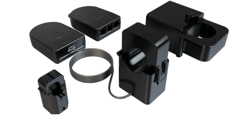
1. Product variants at a glance
|
|
Single Channel |
Three Channel |
|
Channels measured |
1 conductor |
3 conductors |
|
Measurement ranges |
0–60A, 0–200A |
0–60A, 0–200A, 0–600A |
|
Part number |
CTLW_1CH_XXA_XXXX |
CTLW_3CH_XXA_XXXX |
|
Conductor diameter |
60A ≤10mm, 200A ≤24mm |
60A ≤10mm, 200A ≤24mm, 600A ≤36mm |
|
Reporting interval |
Every 30s (standard) |
Every 30s (standard) |
|
Power |
Energy harvesting |
Energy harvesting |
Safety Information
|
Please note Fitting of the CT Clamp must be carried out by a qualified electrical professional, and the mains supply must be isolated prior to any installation. |
2. Key features
-
Measures AC current (50Hz or 60Hz) and reports an averaged RMS value every 30 seconds.
-
Three measurement ranges: 0–60A (±0.1A and 2%), 0–200A (±0.2A and 2%), and 0–600A (±0.5A and 2%) on the Three Channel variant.
-
Self-powered using ultra-low energy harvested from the measured conductor — no batteries and no wiring required.
-
Simply clips around the cable with no interruption to the electrical supply.
-
Transmits data wirelessly via the LoRaWAN® protocol, using internationally approved, licence-free ISM bands.
-
No calibration required.
3. Technical specifications
Measurement
|
Transmission rate |
Reports an average of 5 measurements every 30s (standard operation) |
|
AC frequency |
50Hz or 60Hz |
|
Sampling frequency |
22.6 kHz |
|
Measurement ranges |
0–60A (±0.1A and 2%); 0–200A (±0.2A and 2%); 0–600A (±0.5A and 2%, Three Channel only) |
|
Calibration |
Not Required |
Power
|
Power source |
Energy harvesting — powered by the measured conductor |
|
Low power mode |
1.25A flowing — reports an average of 75 readings every 15 minutes |
|
Standard operation |
1.5A flowing — reports an average of 5 readings every 30 seconds |
Wireless
|
Protocol |
LoRaWAN® Specification 1.0.4 |
|
Device class |
Class A |
|
Radio frequency |
EU868 (863–870 MHz), US915 (902–928 MHz) |
|
Tx power |
+14 dBm (EU868, US915) |
|
Sensitivity |
-146 dBm (EU868, US915) |
|
Security |
LoRaWAN® end-to-end encryption (AES-CTR); data integrity protection (AES-CMAC) |
|
Join method |
OTAA (Over-The-Air Activation) |
Enclosure & dimensions
|
Material |
PC-ABS |
|
IP rating |
IP4X |
|
Transmitter |
80 × 55 × 20 mm (approx) |
|
60A clamp |
25 × 22 × 35 mm (approx) |
|
200A clamp |
35 × 45 × 65 mm (approx) |
|
600A clamp |
65 × 41 × 85 mm (approx, Three Channel only) |
Environment & electrical safety rating
|
Measurement category |
CAT III 300V AC |
|
Maximum system voltage |
CAT III 600V AC |
|
Insulation / protection |
Double insulated, Class II, Pollution Degree PD2 |
|
Operating temperature |
-5°C to +40°C, 0–85% RH |
|
Storage temperature |
-20°C to +55°C, 0–85% RH |
|
Altitude |
Up to 2,000 m |
|
Installation |
Indoor use only |
Compliance
CE approved, UKCA compliant, RoHS compliant, WEEE Directive compliant, and FCC compliant. The product complies with the UK Radio Equipment Regulations 2017 and Directive 2014/53/EU. Applicable standards include IEC 61869-1/-2, IEC 61010-1, IEC 61010-2-030, IEC 61326-1, EN 301 489-1 & 3, EN 300 220-1 & 2 and FCC Part 15 Subpart B and C.
4. Safety information
|
WARNING If this equipment is used in a manner not specified by the manufacturer, the protection provided by the equipment may be impaired. Read these instructions before use and retain them for reference. |
Before you begin
- Installation must be performed by qualified personnel only, in accordance with local regulations.
- Isolate the mains supply before installation.
- Only use the approved clamps provided with the product.
- Ensure the conductor is within the specified current range for the clamp.
- Do not exceed the rated measurement category (CAT III 300V AC / 600V AC max system voltage).
- Do not install on bare conductors unless permitted by the rating.
- Do not use the device if the casing is cracked or damaged.
- Use the device for its intended purpose only, and indoors only. Avoid moisture, dirt, dust, direct sunlight and other heat sources.
- Do not place the transmitter inside a metal case, as this will affect its ability to communicate.
- Do not open the device — there are no user-serviceable parts inside. In case of an error, contact the manufacturer.
Hazard Summary
|
Electrical |
Risk of electric shock if installed on live conductors without proper precautions, or if insulation is damaged or the device is modified. |
|
Mechanical |
Pinch hazard from the split-core mechanism. Incorrect orientation or improper clamping can cause inaccurate readings or unsafe conditions. |
|
Thermal |
Overheating is possible if operated outside the rated current range. |
|
Continuous current limit Part P79.11407 must not be operated continuously above 500A under 65°C. |
5. Physical installation
With the mains supply isolated and the work carried out by a qualified electrical professional:
- Ensure the clamps are clean of debris and dust — wipe them with the alcohol wipes provided.
- Clamp the CT Clamp securely around the live conductor. Make sure the clamp is fully closed during operation.
- Connect the RJ11 connector(s) to the transmitter securely. Channel numbers are printed on the product label on the transmitter (channels 1–3 on the Three Channel; channel 1 on the Single Channel).
- For best wireless transmitting range, install the transmitter outside of the electrical enclosure.
|
Note The clamps clip around the conductor with no interruption to the electrical supply. Ensure each conductor is within the measurable diameter for its clamp: 60A ≤ 10mm, 200A ≤ 24mm, 600A ≤ 36mm. |
6. Product activation
The unit is 100% energy harvesting, so it can only perform a self-powered join once it is clipped around a conductor and the minimum required current is flowing. The minimum join current is 1.5A flowing for all measurement ranges.
- Clip the CT Clamp around the conductor.
- Wait for a period of 15 minutes. The device will attempt to join the configured LoRaWAN Network Server (LNS).
- On a successful join, the LED will briefly flash GREEN.
Time to join
Higher current through the conductor charges the device faster, reducing the time to join:
|
Current flowing |
Time to join |
|
1.5A |
15 minutes |
|
3A |
5 minutes 30 seconds |
|
5A |
3 minutes 30 seconds |
|
10A |
2 minutes |
|
20A |
1 minute 30 seconds |
Measured join and transmission times
The chart below shows measured test results: the time taken from power-on to the join message, the first transmission (Tx 1) and the second transmission (Tx 2), across a range of conductor currents. As current increases, the device harvests energy faster, so join and transmission times fall sharply before levelling off above ~5A.
Figure 1: Time from power-on to join and transmission, by conductor current (measured test data).
7. Commissioning on a LoRaWAN Network
- Ensure your sensor is powered and within range of your LoRaWAN gateway or receiving device.
- Input the DEV EUI, APP KEY and JOIN EUI into your LoRaWAN Network Server.
- Attach the current clamps to a live conductor. Once sufficient current is present, the sensor connects to the network via OTAA.
- Once connected to the LNS successfully, the LED will flash GREEN.
Decoding the data
Once the sensor is added to your LoRaWAN Network Server, decode the information using the Pressac LoRaWAN Sensor Decoder, available on our Github.
8. Operating modes
The sensor automatically switches between two modes depending on the current flowing through the conductor.
Standard operation (≥ 1.5A)
The sensor takes a sample reading every 6 seconds and reports an average RMS current value every 30 seconds.
Low power mode (~ 1.25A)
When around 1.25A is flowing, the sensor enters low power mode: it takes readings every 12 seconds and outputs data in 15-minute intervals. When fully charged with no current flowing and operating on SF7, the charge lasts up to 8 hours in low power mode. Once the circuit reaches 1.5A, the sensor returns to standard operation.
9. LED indication
Standard operation
|
Operation |
Indication |
Interval |
|
Sample |
Faint green flash |
6s |
|
TX acknowledge |
Bright green flash |
30s |
|
TX no acknowledge |
Bright red flash |
30s |
Low power mode
|
Operation |
Indication |
Interval |
|
Sample |
Faint green flash |
12s |
|
TX acknowledge |
Bright green flash |
15m |
|
TX no acknowledge |
Bright red flash |
15m |
10. Factory reset
To factory reset the device while it is powered, hold down the button on the front of the device for 12 seconds. Once the process is complete the LED will flash RED three times, finishing with one GREEN flash. The flash memory will then be reset.
11. Maintenance, cleaning & inspection
Periodic inspection
Periodically inspect the device for cracks in the housing, cable damage and a loose hinge mechanism. Replace immediately if any damage is observed.
Cleaning
- Disconnect power before cleaning.
- Clean the enclosure using a 70% Isopropyl Alcohol (IPA) wipe.
- Do not apply liquids directly to the sensor intake vents.
- Do not allow liquid ingress into the RJ11 ports or internal circuitry.
- Contact the manufacturer if you are unsure about cleaning agent compatibility.
Disposal (WEEE)
This product must not be disposed of as unsorted municipal waste. Dispose of it in accordance with local regulations using designated electrical/electronic waste collection systems. Proper disposal helps prevent environmental and health risks.
12. Troubleshooting
|
Symptom |
Likely cause & action |
|
Device will not join the network |
Insufficient current. The unit needs at least 1.5A flowing to power itself and join. Confirm load is present, then allow up to 15 minutes (less at higher current — see Time to join). |
|
No LED activity at all |
No harvested power. Verify the clamp is fully closed around a live conductor carrying current, and that the RJ11 connector is securely seated in the transmitter. |
|
Repeated red TX flashes |
Transmissions are not being acknowledged. Check gateway range and that the transmitter is outside the metal enclosure; relocate the transmitter if needed. |
|
Inaccurate readings |
Check clamp orientation, ensure the clamp is fully closed, and confirm the conductor is within the rated current range and diameter for the clamp. |
|
Credentials rejected by LNS |
Re-check the DEV EUI, APP KEY and JOIN EUI entered into your Network Server match the device. |
|
Returns to 15-minute reporting |
The circuit has dropped to ~1.25A and the device has entered low power mode. It returns to 30-second reporting once current reaches 1.5A. |
13. Support & contact
|
Sales |
sales@pressac.com · +44 (0) 115 936 5200 |
|
Support |
support@pressac.com · +44 (0) 115 936 5202 |
|
Support portal |
support.pressac.com |
|
Web |
www.pressac.com |
|
Address |
Pressac Communications Ltd, 145 Glaisdale Drive West, Nottingham, NG8 4GY |