
Product description
The pulse counter is designed to count the pulse output from a standard electricity, water or general meter. It sends an EnOcean telegram containing an accumulative pulse count from the equipment it is connected to.

Product operation
The pulse counter will send a telegram containing the cumulative pulse count relevant to the EEP set. When set to A5-12-01, the counter will report in kWh, A5-12-00 reports in counts and A5-12-03 reports in m³. It will send a telegram once the pulse per count has been reached for the set EEP.
Available variants
| Frequency | Frequency Type | Part Number |
| 868MHz | EnOcean for Europe | PCTR_E868_S |
Installation
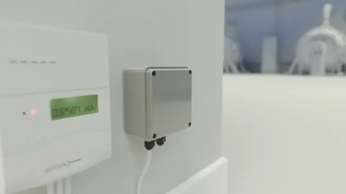
The pulse counter can be mounted either with the provided sticky pads or the screw kit (which includes O-rings for additional IP protection). We recommend mounting it on a vertical non-metallic surface, with the cable entry gland facing downwards.
The wires going in the pulse counter from the meter should not be wrapped around any other wires as this can cause electrical interference to the pulse count.
The mounting holes are located inside the case. The lid can be taken off by removing the four screws on the top and carefully lifting off. To screw the pulse counter to the wall, the mounting hole needs to be drilled out using a 4mm drill bit.
Note: The preferred method for mounting is using the four stick pads provided.
Connection of pulse counter
The cable entry gland on the base of the pulse counter is designed for the entry of a 0.3mm to 2mm cable. To ensure the overall IP rating of the sensor only one cable should be fitted. Ensure the gland is fully tightened.
The minimum period between pulses is shown in the table below:
| Symmetrical Pulse | Asymmetrical Pulse | |
| TTL | ||
| On Time(ms) | 90 | 10 |
| Off Time(ms) | 90 | 90 |
| O/C | ||
| On Time(ms) | 60 | 90 |
| Off Time(ms) | 60 | 10 |
The connection block on the pulse counter PCB has screw terminals. To insert the cables, use a small Phillips head screwdriver.
Connections: TTL, O/C, GND, GND, 5V_OUT and 7-24V IN.
When powering externally use the GND and 7-24V IN terminal block. The maximum rating of the power supply should be 24V, 1A.
Tip: Please ensure that the installation of the pulse counter is done by a competent person.
Note: The 5v DC output will only be active when the unit is powered by +7-24v DC.
Changing the battery
Estimated battery life using default settings, assuming average use, can be found in the technical specification section of this document. Changing the battery can be done by following the steps below.
- Remove the four screws from the lid of the unit and gently remove the lid.
- Replace the battery in the battery holder.
- Reassemble the device, replace the four screws on the lid of the device and gently tighten.
Note: Whilst the battery is being changed, no pulses will be counted.
Activation
External power
When powered externally, DIP switch 1 does not need to be in the ON position the device will be powered on as standard. This will be indicated by LED 2 being illuminated.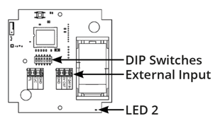
Battery
You need to turn the pulse counter on prior to first use. You can do this by removing the top cover and switching DIP switch 1 to the ON position. The battery should not be used as a backup if the device is externally powered.
Secure mode
The pulse counter includes an enhanced secure mode. When secure mode is turned on, all EnOcean radio communication is encrypted by AES128. For more information, EnOcean’s full security specification can be found on https://www.enocean.com.
Switching between modes
Note: Before changing the pulse counter’s operating mode, you need to remove the device from all receiving devices it has been configured to work with. Failure to do so could result in ignored telegrams.
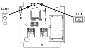
The pulse counter can be switched between standard mode and secure mode by pressing the learn button for at least 10 seconds. The devices mode will be changed when the learn button is released.
Tip:
- Secure mode is indicated by the LED flashing GREEN four times.
- Standard mode is indicated by the LED flashing RED four times.
The pulse counter is delivered in standard mode with encryption turned off.
Commissioning
Adding the pulse counter to an EnOcean radio network.
Note: If including a pulse counter in secure mode please ensure your receiving device is EnOcean security compatible.
- Ensure your pulse counter is within range of your EnOcean gateway or receiving device.
- Place your EnOcean gateway or receiving device into inclusion mode.
- Press the button on the pulse counter and the LED will blink green twice. The device will now transmit a teach in telegram
- Wait for the teach in process to end. Please allow extra time if using secure mode.
- Successful inclusion will be indicated on the EnOcean gateway or receiving device.
The pulse counter can also be included into your EnOcean network manually. This can be achieved using the unique EnOcean ID and the EnOcean Equipment Profile (EEP). The EnOcean ID and EEP are printed on the product label.
Remote management and commissioning (ReCom)
A signal telegram indicating the pulse counter is available to remote unlock for one second is sent after every learn telegram, and when the device is powered on.
Successful remote unlock will be indicated by a single flash of both LEDs.
Note: The default unlock code is 87735522.
Action command
Sending the action command will help identify the pulse counter by the LEDs alternately flashing red and green for six seconds.
Note: A copy of the latest device description file can be downloaded here:
DDF_PULSECOUNTER_868MHz.zip
DDF_PULSECOUNTER_902MHz.zip
Configurable options via remote commissioning
| OPTION | CONFIGURABLE | DEFAULT |
| EEP Selection | A5-12-00 (Count) A5-12-01 (kWh) A5-12-03 (m3) |
A5-12-00 (Count) |
| Pulses Per kWh | Between 1 -10000 Pulses per kWh | 1000 Pulse per kWh |
| Pulses Per | Between 1 -10000 Pulses per m3 | 1000 Pulse per m3 |
| Pulses Per Count | Between 1 -10000 Pulses per Count | 1 Pulse per Count |
| Pulse Count Divisor | 1,10,100,1000 | 1 |
| Pulse Count Reset | True or False | False |
| Signal Telegram Transmission | Between 0 – 65535 Sample Pulses | 0 |
Restore factory settings
Setting DIP Switch 2 and 3 to the ON position and holding down the LEARN button for 30 seconds will initiate restoration of the default settings and default remote management unlock code. This will include setting the count to 0.
While a restore is in progress, the LED will flash RED four times followed by a GREEN LED flicker if successful or a RED LED flicker if unsuccessful.
DIP switch functionality
DIP switches will be read and stored in EEPROM upon a learn button press.
DIP switch 1 = Device ON/OFF
DIP switch 2 = Sets EEP
DIP switch 3 = Sets EEP
DIP switch 4 = Sets count rate
DIP switch 5 = Sets count rate
DIP switch 6 = ReCom ON and OFF
Below are the different combinations for the DIP switches.
| SWITCH 2 | SWITCH 3 | EEP |
| OFF | OFF | A5-12-00 (AMR Counter) |
| OFF | ON | A5-12-01 (AMR Electricity Sensor) |
| ON | OFF | A5-12-03 (AMR Water Sensor) |
| ON | ON | Factory Restore |
| SWITCH 4 | SWITCH 5 | PULSES PER * | DIVISOR |
| OFF | OFF | 1 | 1 |
| OFF | ON | 10 | 10 |
| ON | OFF | 100 | 100 |
| ON | ON | 1000 | 1000 |
Note: *Pulses per kWh, m³ and Count.
Technical specifications
| Wireless protocol | EnOcean |
| Security and encryption | AES-128 Configurable ON/OFF |
| Remote commissioning | Yes |
| Repeater | No |
| Telegram | 4BS |
| EEP | A5-12-01, A5-12-03 and A5-12-00 |
| Battery life* | Typically 1 year |
| Battery type | C Size 3.6v Lithium |
| Powering | +7-24V** / Battery |
| Environment | IP55 |
| Mounting | Screws or Sticky Pads |
| Enclosure material | Technopolymer Case and Lid |
| Operating temperature range | 0°C to +40°C |
| Storage temperature range | -20°C to +55°C |
| Dimensions of case | 108x131x58mm approx. |
Note: *Typical life expectancy of the battery is dependent on use-case.